
In order to preserve a cold, stable environment for the HPF optics, the entire instrument must be kept in a giant vacuum chamber, called a cryostat. The cryostat must seal out the ambient atmosphere for years at a time, while simultaneously maintaining a rigid shape against the enormous forces of the external air pressure working to crush it like a soda can. Needless to say, this is quite a challenge both to design and build! Despite minor delays with regard to the machining of individual parts, the three primary assemblies for the cryostat shell are progressing very nicely, and are extremely close to completion. Let’s take a closer look at the cryostat and its component parts.
The vacuum boundary is comprised of three assemblies. The box frame, the upper hood, and the lower hood.
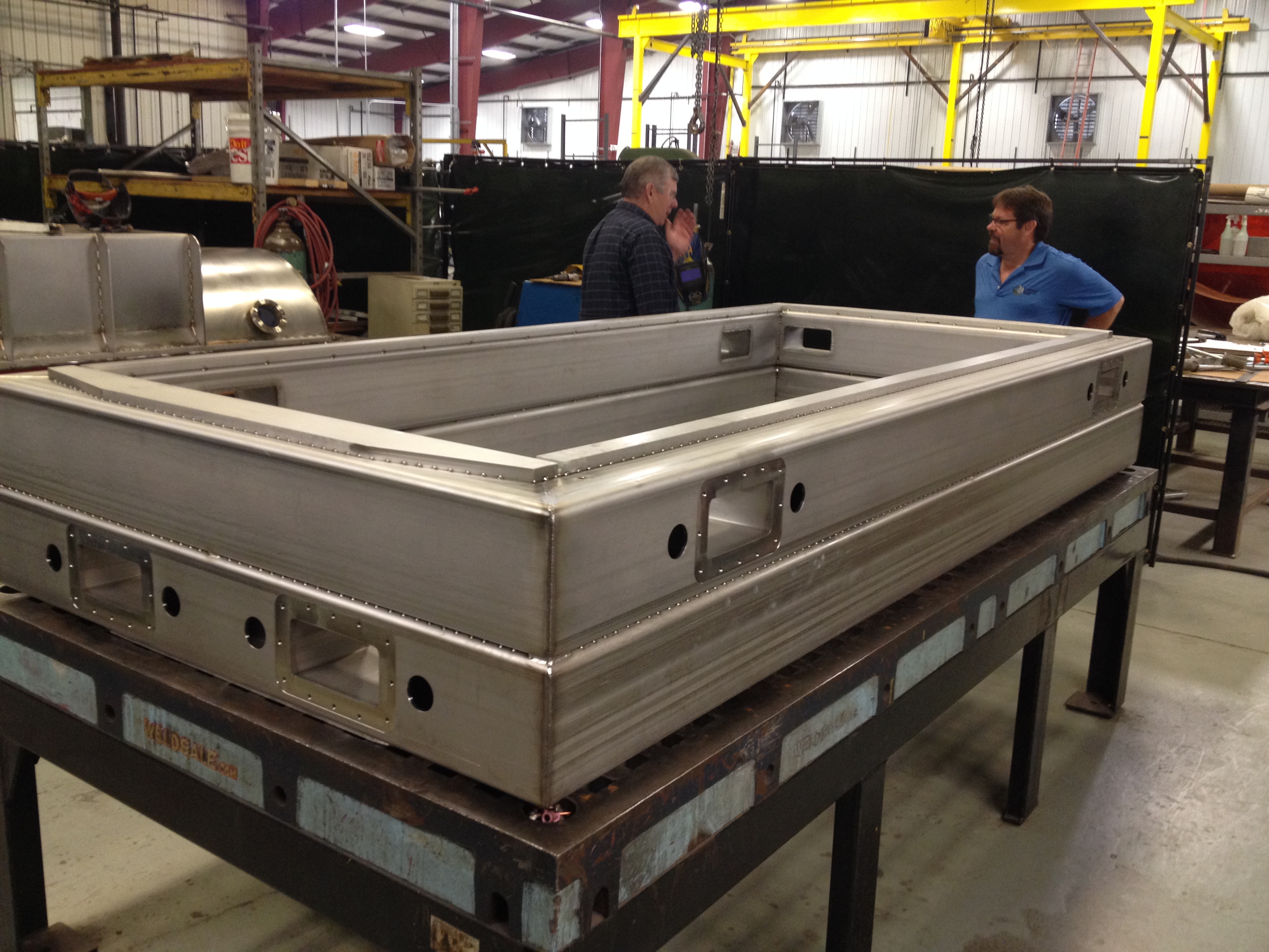
Here we see the box frame assembly. The ½” thick stainless steel perimeter seen on the top face of the upper box frame members will soon be machined to receive the large o-ring, responsible for keeping out as many air particles as possible.
When two components are welded together, they tend to distort relative to one another. Even with high capacity restraints, this fact is inevitable and unavoidable. The only thing one can do is to acknowledge that this distortion will take place, and plan accordingly. In this case, when the ½” plates are welded to the top of the box frame, and in fact even when the two sections of box members are welded together, they warp slightly. This is an issue, because in order to achieve uniform compression of the o-ring, this face must be as close to planar as possible. An o-ring is quite simply a rubber material, with a spherical cross section. When the o-ring is compressed between two plates, it fills any tiny imperfections in the surface of the plates. If done properly, an o-ring can be extremely good at keeping air out, allowing the HPF team to keep an extremely stable vacuum pressure within the cryostat. So in order to overcome the distortion induced by welding, and to achieve the flatness on this o-ring face that is required, the entire assembly you see in the photo above will be placed on a planar mill. The assembly will be restrained on the table, and the mill will then take several cutting passes, removing the upper layer of material, and leaving a surface that is flat to within 5 thousands of an inch (about the thickness of a dollar bill!). This same process will be repeated for both the upper and lower hoods, ensuring that any mating faces are as flat as possible.
The construction of the cryostat is truly an impressive process, and really must be seen to be appreciated. Below, please enjoy some photos from our recent trip to the shop!

Tack welds secure the o-ring plate during the welding process. The entire assembly is tack welded together, followed by stitch welds (connecting sets of tacks), or continuous welds where necessary.
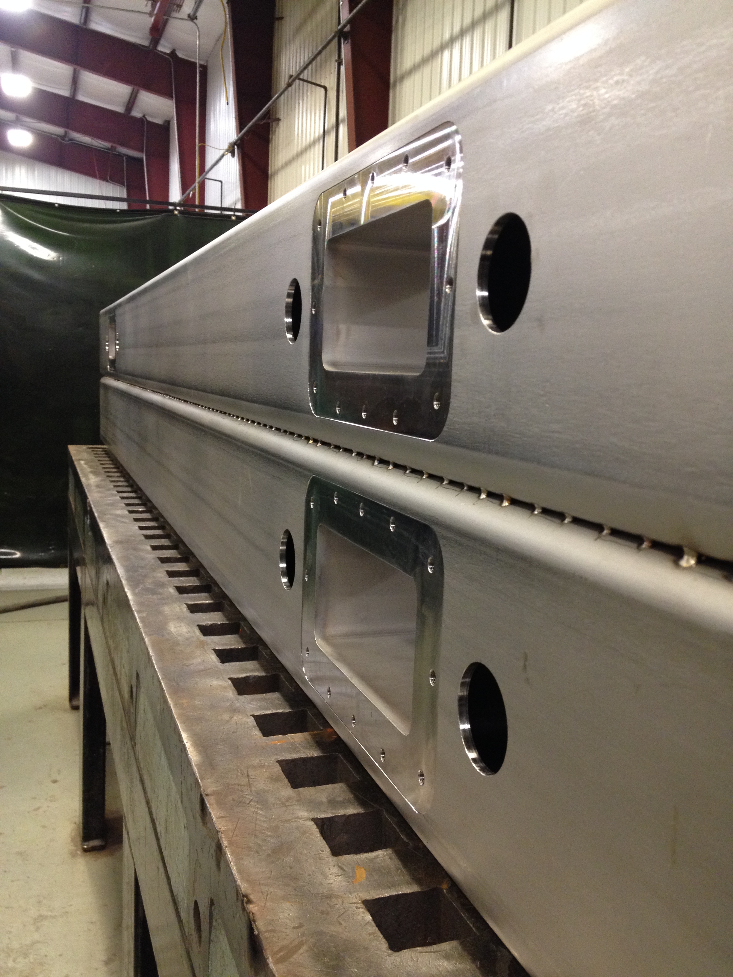
Here is a set of vacuum feed-through locations. A metal plate with an o-ring will bolt onto these faces, which you can see have been milled flat. By mounting hermetically sealed electrical connections on the metal plate, we are able to run wires and optical fibers into the instrument, as well as all necessary plumbing accessories.
Checking the flatness of the top surface. The end caps were still not tack welded in place.
Beautiful work

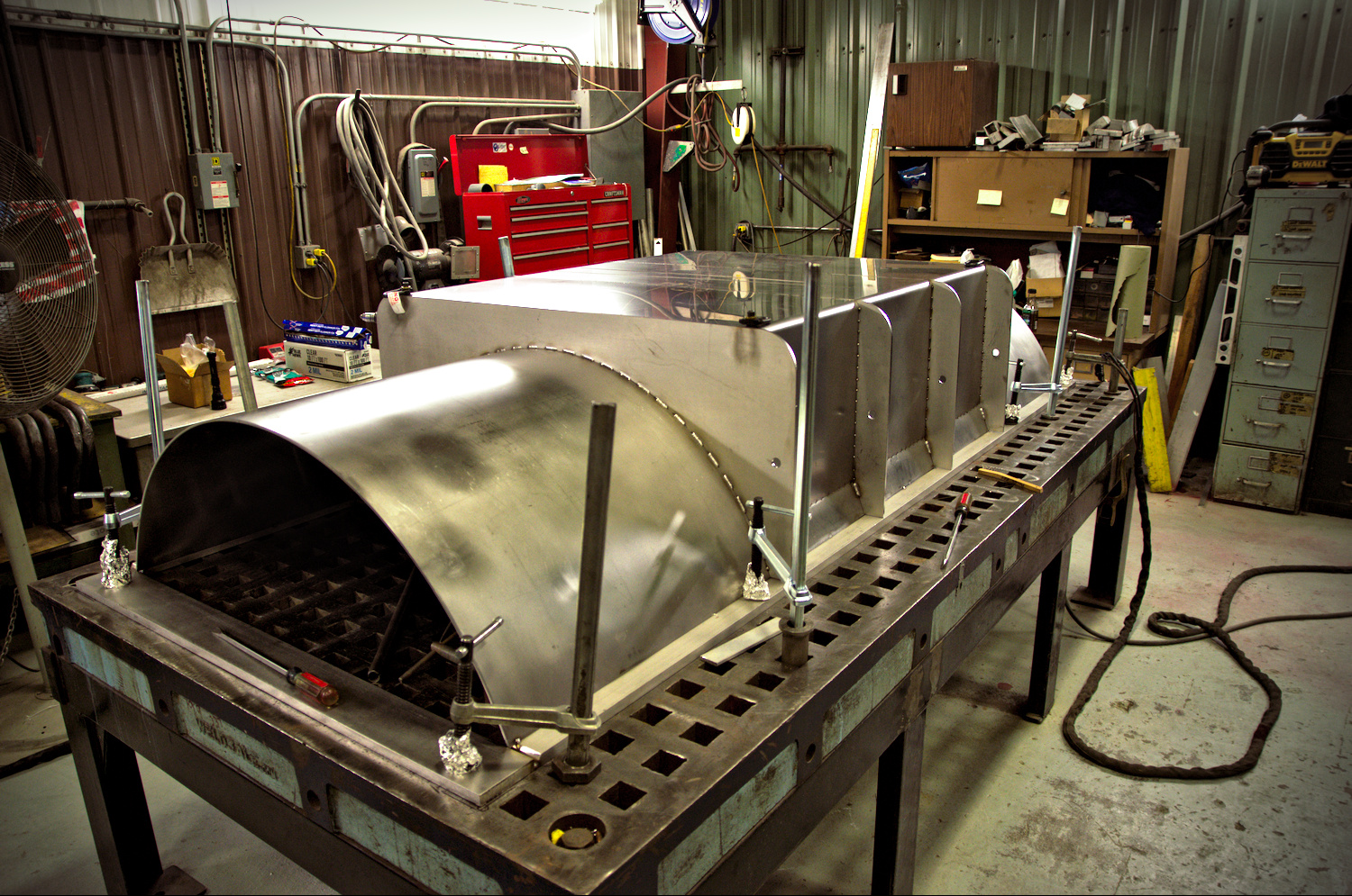
Part of the HPF team discussing the welding progress on the upper hood. You can see the large clamps spaced around the perimeter, holding components in place during welding. Notice the aluminum foil wrapped around the clamps… always trying to keep things as clean as possible!
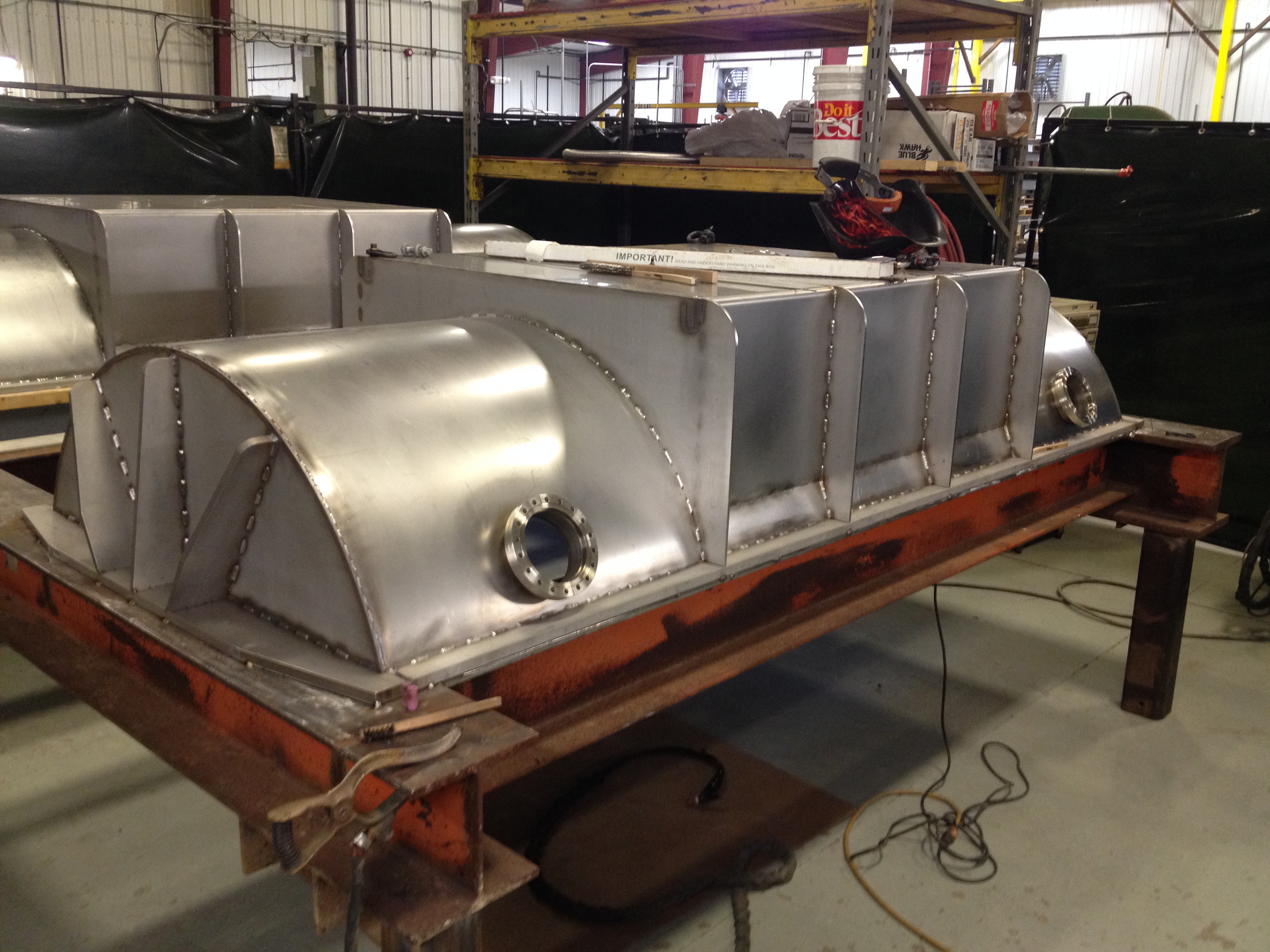
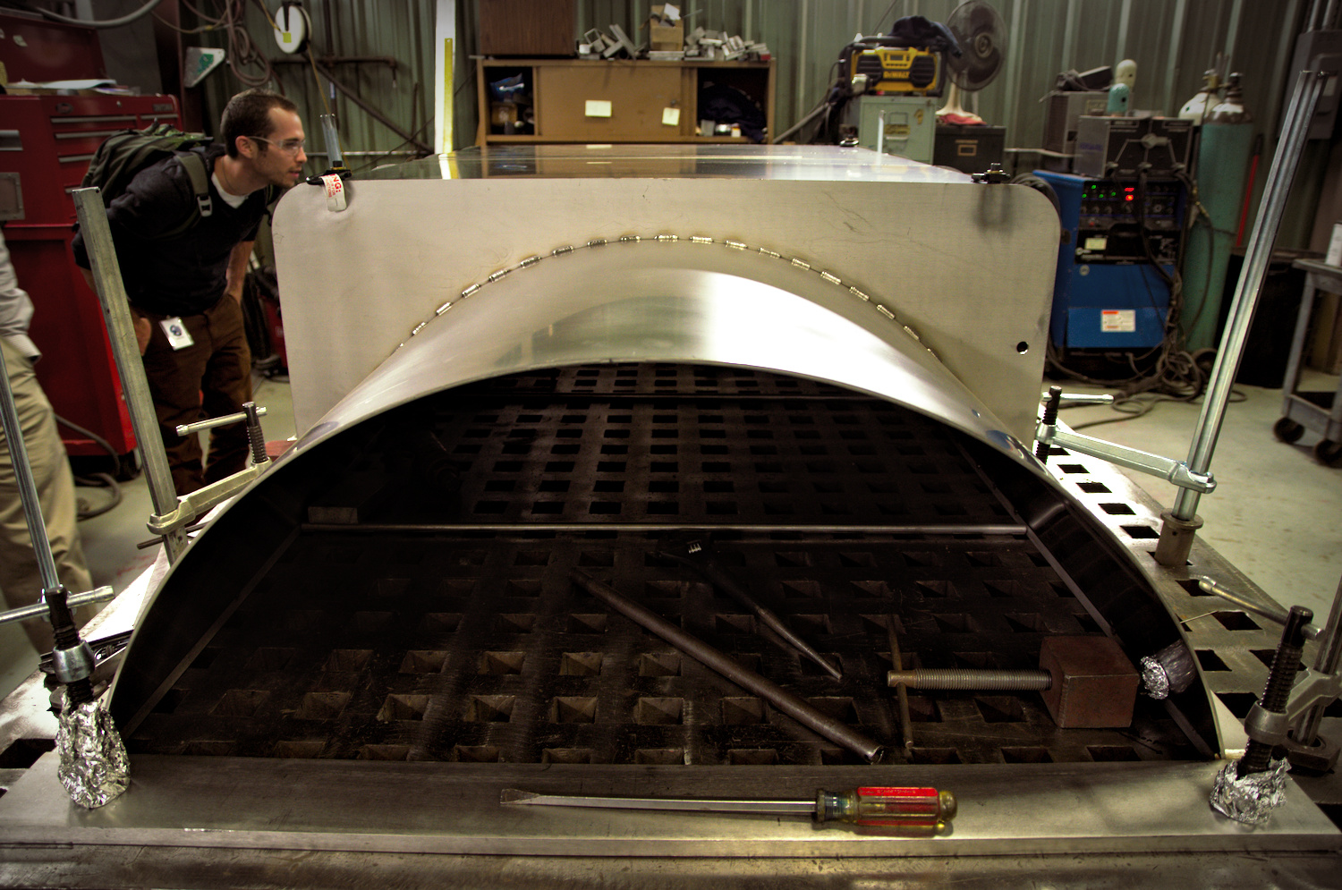
This is the lower hood. It is nearly identical to the upper hood (seen in the background), except that it has 4 symmetrically placed circular penetrations. These will accommodate brackets designed to restrain the bench during shipment, keeping it from slamming into the cryostat body. Once the instrument is ready for operation, plates with gaskets will seal these 4 penetrations.
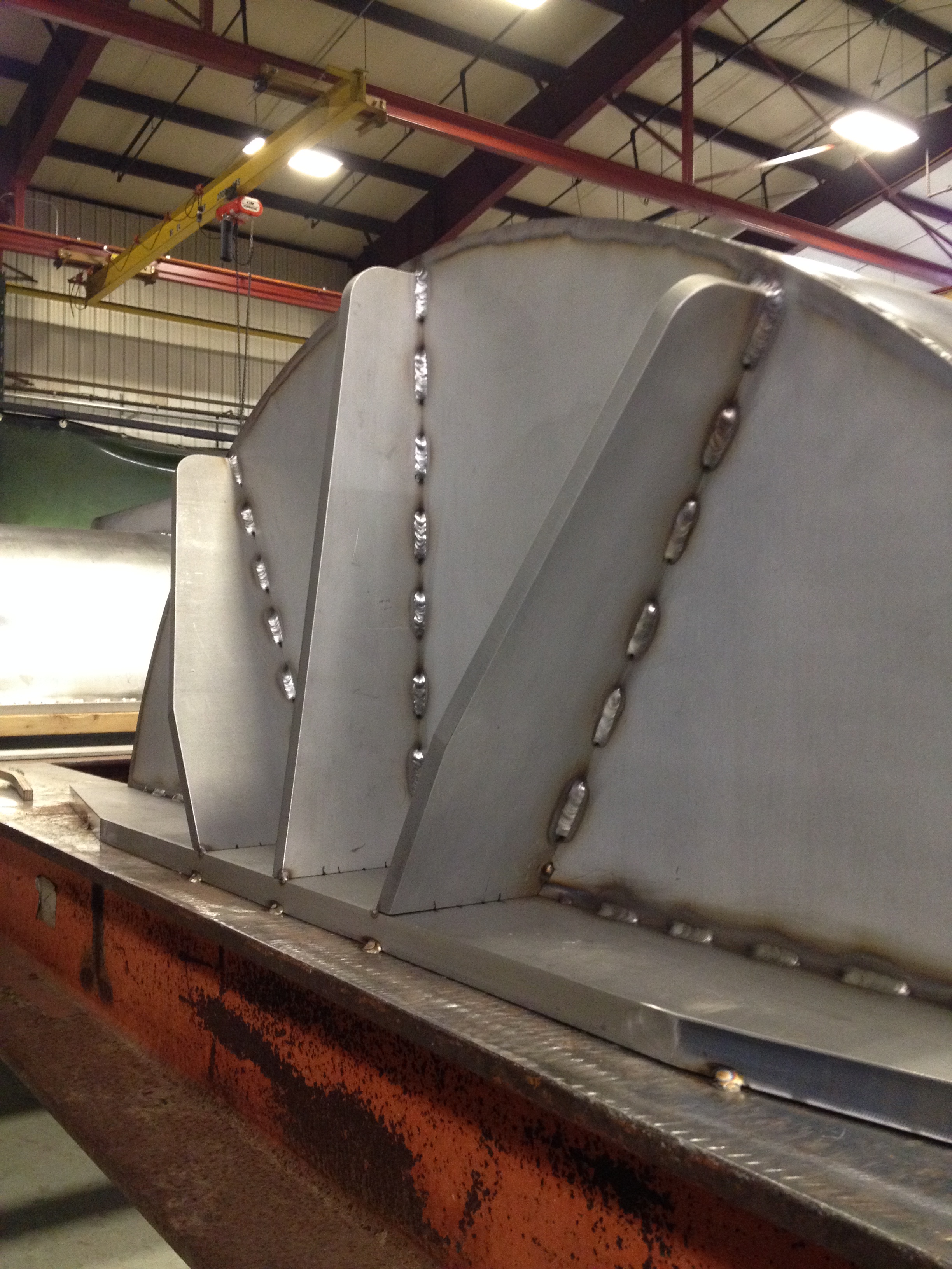
Close-up of the end cap and support webs. When vacuum is drawn, these caps tend to deform into the cryostat volume. These three webs act as I-beams, keeping the ends from collapsing inwards. You can clearly see where the plate at the bottom of the photo was tack welded to the support beams, keeping it in place during the assembly process.
 RSS - Posts