
Background: the need to cool HPF down to 180K
One of the most frequently discussed topics on this blog has been the need to enclose the HPF instrument in a stable, cold environment. Because HPF will observe stars in infrared light, it is essential to remove as much of the thermal infrared radiation from the system as possible, and keep the rest absolutely constant. We achieve this by placing the entire instrument in a vacuum chamber (known as a “cryostat”) and cooling it to 180K (-93.15° Celsius).
Previous posts on the HPF blog have covered the theory of our thermal control system and the design of our vacuum cryostat. Since posting those articles, we have been hard at work bringing this system off the spec sheet and into the lab. The cryostat is now pumped down, and the environment control system (ECS) is running. Let’s look at the results!
Easier Said Than Done
Very briefly, our cryostat is designed to maintain a constant temperature by cooling the instrument to about 170K using copper thermal straps connecting the optical bench to a tank of liquid nitrogen, then warming back up to 180K with electrical heaters controlled by a custom computer system. Below is a schematic of the basic ECS operation.
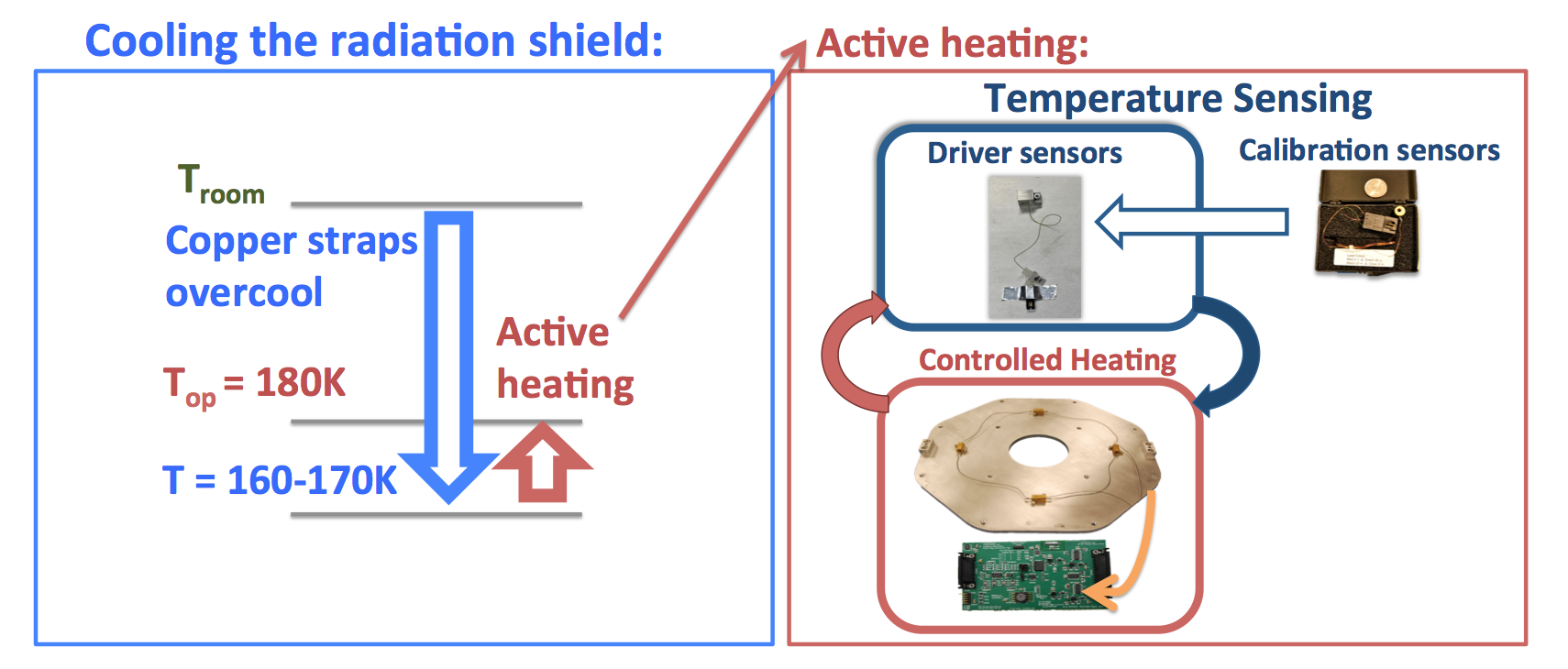
A schematic of how the HPF Environment Control System (ECS) maintains a constant 180K instrument temperature.
Every step of this process requires specialized hardware and careful attention to detail. We showed you the construction of the thermal straps and electrical heaters in a previous entry, but let’s look at some other aspects of the system that are now in place.
While we are unable to verify officially, we are reasonably confident that HPF has more internal electronics and wiring than any previous astronomical spectrograph with no moving parts. The temperature sensors and heaters seen in the schematic above are simple enough devices on their own, but managing the wiring for the approximately 65 such units in a vacuum chamber can be quite the tangle. We made dozens of custom wiring harnesses with specialized vacuum feed-throughs to connect our cryostat to the outside world.
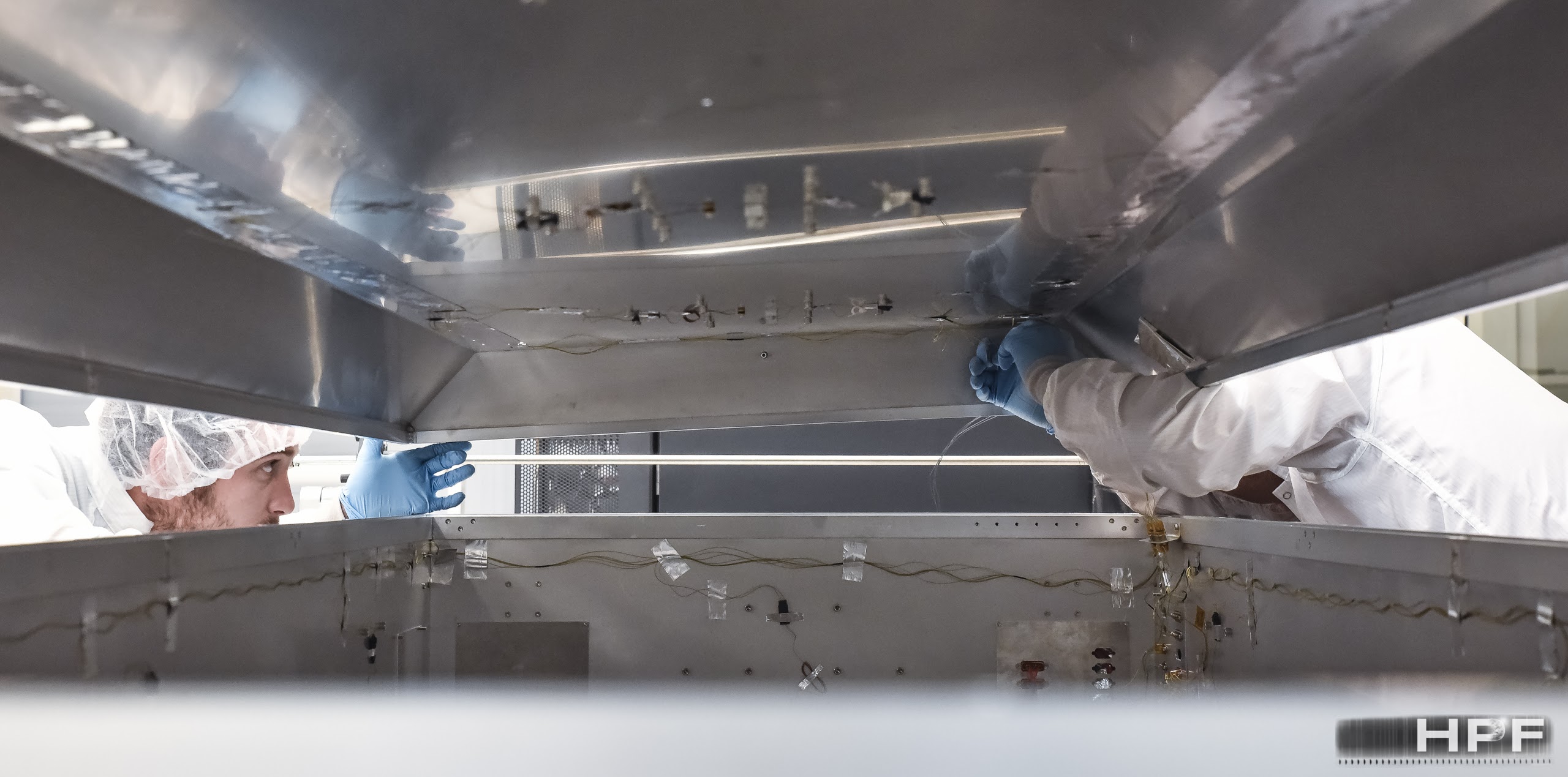
Eric Levi and Paul Robertson make the final electrical connections before closing the radiation shield lid.
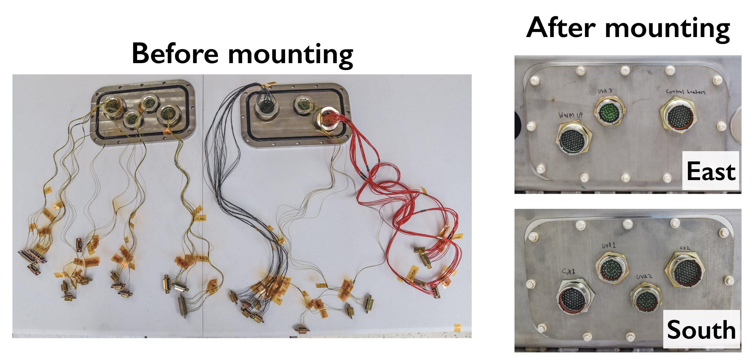
Vacuum feed-throughs for the HPF cryostat. Note the number of wires!
Additionally, achieving vacuum pressures of 10-7 Torr is not as simple as hooking up your household dust buster. We need two separate pumps: one “roughing” pump to remove the first 99.99999% (!) of the air, and then a high-speed “turbo” pump to get us the last three orders of magnitude. When you add in the accompanying safety valves and vacuum gauges, the cryostat and its vacuum components start to take up quite a bit of space and power.
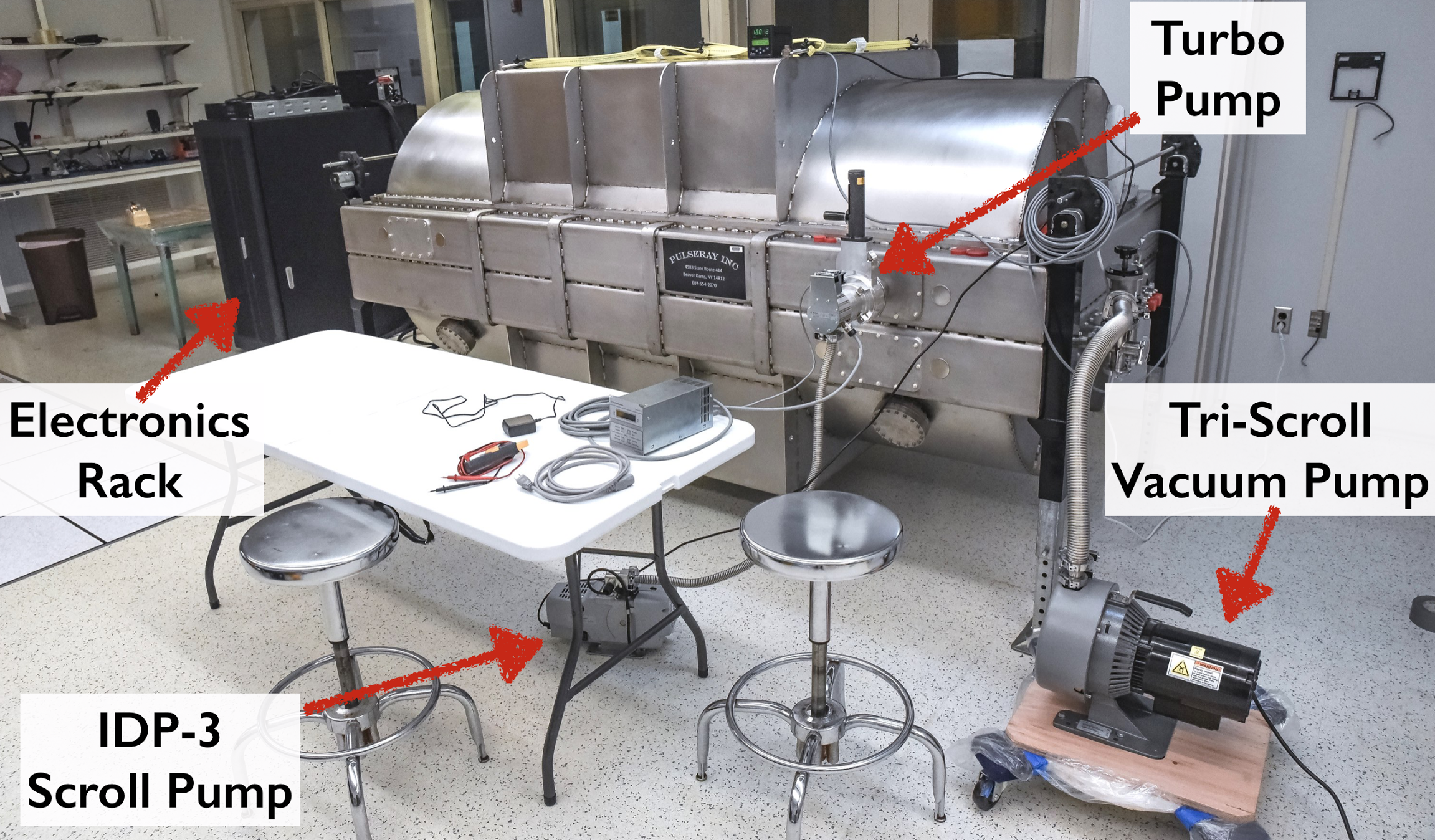
The HPF vacuum pumps and electronics rack.
So, does it all work?
A system this complex—with so many components that have to work in concert to achieve the desired results—gets road-tested in incremental stages. Our first full-scale environment control test was a “warm test”, designed to test the vacuum and electronic systems. In this mode, we disconnected the copper thermal straps from the optical bench and attempted to maintain temperature stability near room temperature. Rather than use the liquid nitrogen tank as a heat sink, we used the heaters to raise the internal temperature about 10 degrees above room temperature, and used the entire ambient environment as the heat sink. The liquid nitrogen tank is still filled, but only to cool the activated charcoal getters that maintain our exquisite vacuum.
A secondary motivation for the warm test is our ongoing instrument concept design for NASA’s upcoming Extreme Precision Doppler Spectrograph, or EPDS. Our HPF team is one of two finalist groups competing to build the instrument. Because the EPDS spectrograph will use optical wavelengths (as opposed to HPF’s near-infrared coverage), it can be operated near room temperature, as the thermal background does not affect the visible spectrum. However, EPDS still requires excellent temperature stability, hence our adaptation of the HPF concept to warmer temperatures.
We just completed a two-week warm stability test, and we are beyond excited with the results. Over the entire two-week run, the cryostat was stable to less than a milliKelvin! Better yet, over a typical 24-hour period, our RMS stability is closer to a tenth of a milliKelvin. For HPF, this exceeds our needed stability by about a factor of ten, giving much-needed assurance that the cryostat will provide a suitable environment for precision Doppler spectroscopy.
Without further ado, here are the data!
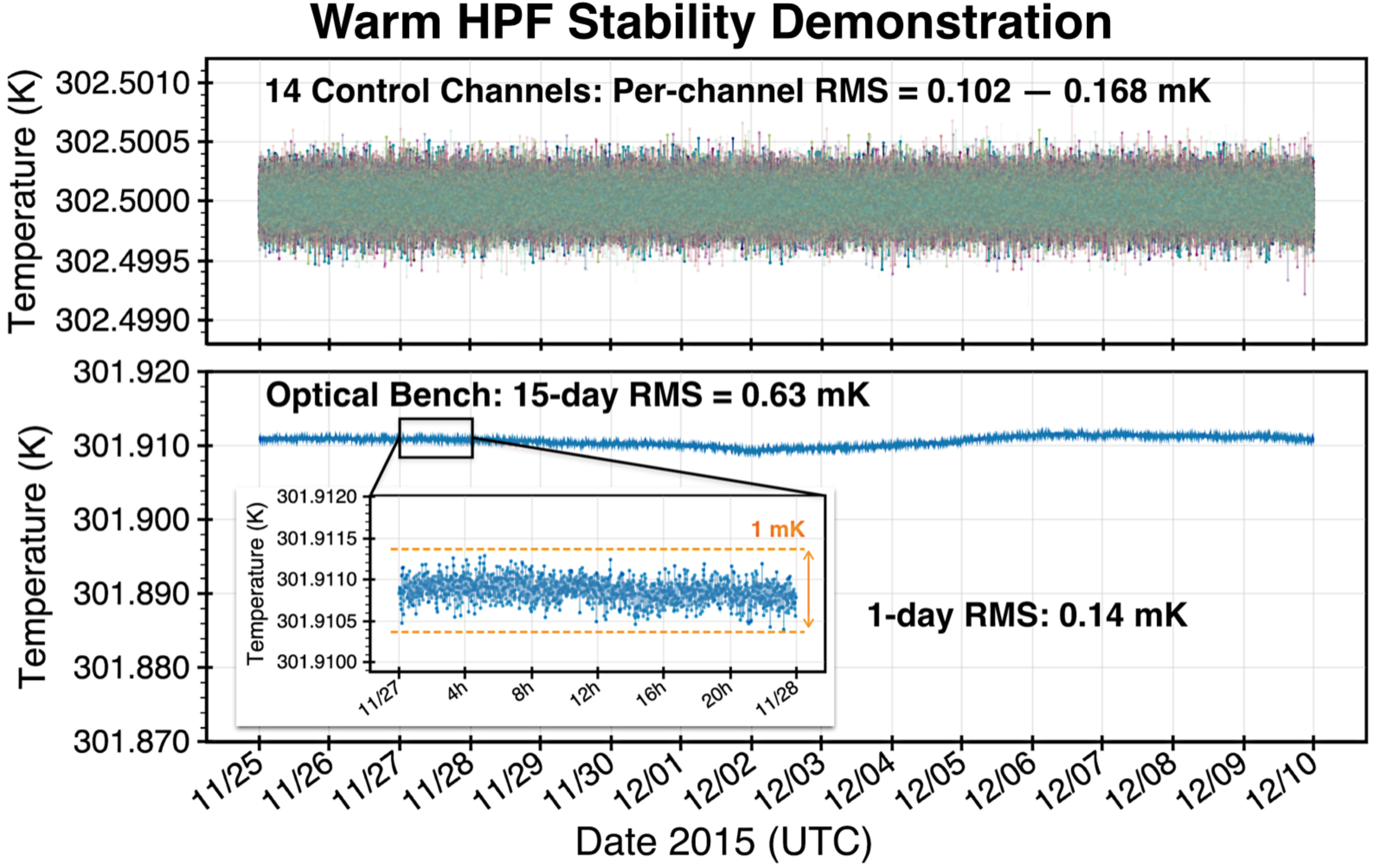
Results from a 2-week warm temperature stability test. All 14 active control heaters remained stable to within 0.2 milliKelvin, while the optical bench maintained sub-milliKelvin stability, and exceeded 0.15 mK stability over 24 hours.
Even with this encouraging result in hand, we know we can do better. The longer-term fluctuations seen in the plot above are caused by ambient pressure changes, which we will mitigate by installing a pressure regulator on the liquid nitrogen tank. And remember, this system is designed to operate at 180 Kelvin!
Next up: the cold test. The thermal straps are reattached, and the liquid nitrogen is flowing. Stay tuned!
 RSS - Posts