
Now that you know what HPF is, and what its primary science functions will be, let’s take a closer look at some of the hardware that makes the exciting science possible. The cryostat–basically, a cryogenic vacuum chamber–is fed light from the telescope via an optical fiber, which then passes through the spectrograph optics before being imaged onto the infrared detector. “But wait,” you might ask, “if this is infrared light we’re trying to detect, how do you filter out the infrared light being emitted from around the room?” After all, warm objects emit infrared. This phenomenon, where too much IR light reaches a detector face, is known as saturation. So much IR reaches the detector, that it becomes impossible to discern the spectra of one object from the next. To remedy this, we build a vacuum chamber. This is the exoskeleton that will house all of the optics, keeping them cold and isolated from the rest of the world. Remember, we’re trying to maintain 1 milliKelvin stability (5 parts per million!), and so the more control we have over heat transfer within the system, the better. The cryostat vacuum chamber is a right circular cylinder, with a rectangular flange which allows the upper and lower lids to be removed. Air is evacuated from the chamber; the pressure within reaching 10-7 millitorr levels.
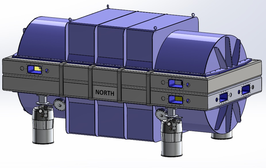
Full Cryostat, resting on isolation legs.
There are 3 modes of heat transfer, and they govern all heat transfer throughout the universe: conduction, convection, and radiation. Conduction is the transfer of heat through physical contact. Convection is the transfer of heat through a liquid or gas medium surrounding an object. Radiation is the transfer of energy through photons.
In an ideal world, the HPF cryostat would eliminate all three of these heat transfer modes. In reality, we can only limit their effects, but cannot altogether eliminate them. In order to limit conductive pathways from the optical components to the surrounding cryostat shell, we use a small cross section suspension system. A set of 3 “hangers” allows the bench, with the optics mounted on top, to be nearly conductively insulated from the surrounding cryostat body. This three point mounting system also allows the bench to thermally contract, without inducing any stresses on the system, which would wreak havoc on optical alignment.
By evacuating air from the cryostat, we essentially eliminate convective heat transfer. Without air surrounding the optics, there is no medium to flow over the optical components and transfer energy. That leaves us with radiation, our primary concern. In order to keep the detector from being saturated with IR radiation, we must keep all objects that the detector sees extremely cold… 180 Kelvin (-136 degrees Fahrenheit) cold.
To isolate the optics from the surrounding world, a radiation shield is employed. This radiation shield acts like a buffer between the cryostat body, and the optical components residing inside. With the use of multi-layer insulation blankets made of highly reflective material, the radiative load on the shield will be decreased to a level of 3.5 watts per square meter. The radiation shield is coupled via 16 thermal straps of copper foil to a liquid nitrogen tank, effectively creating a large heat sink. The copper straps are sized in such a way that the equilibrium temperature of the radiation shield is 175 degrees Kelvin. To get the shield to be 180 K, we use a set of 14 heater panels, adding just enough heat to control the shield to 180 K. With the optics now being surrounding by material at 180 K, they too will drift to a temperature of 180 K.
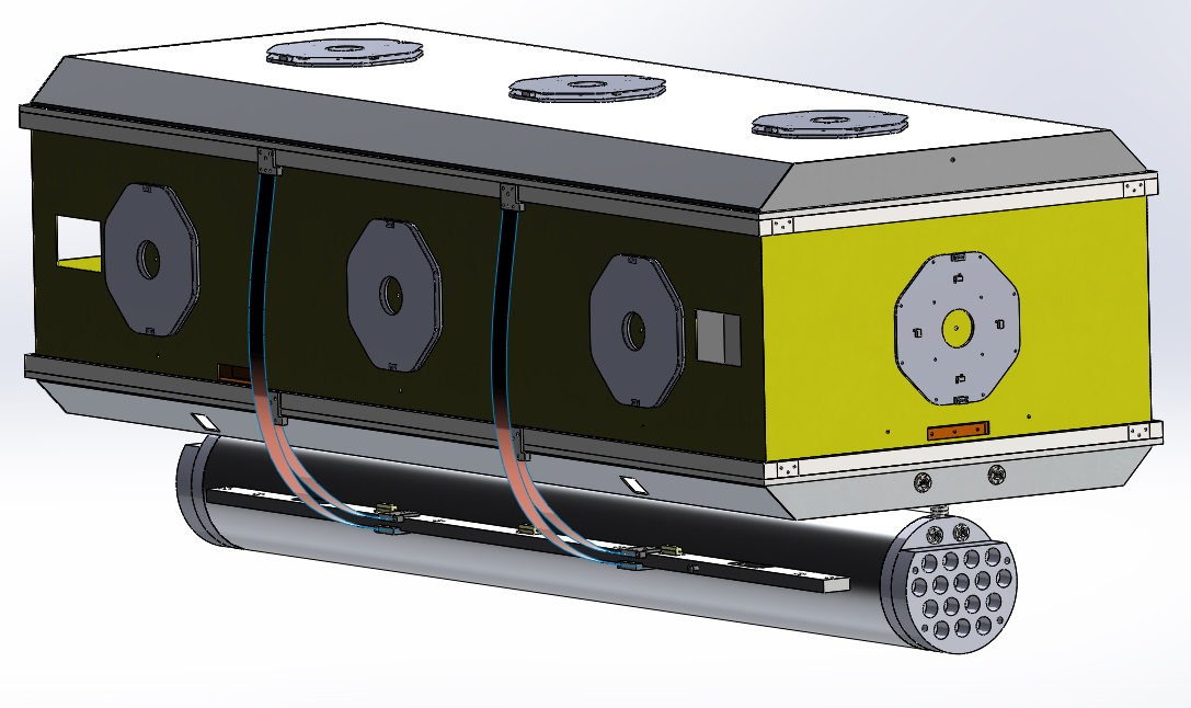
Radiation shield with liquid nitrogen tank, heater panels (stop sign shapes), and thermal straps connection nitrogen tank to radiation shield.
By putting the optics in a vacuum chamber, limiting the conductive paths, and actively controlling the radiation shield temperature, the HPF team will be able to achieve 1 milliKelvin temperature stability over long time scales.
 RSS - Posts