Three members of the HPF team recently visited McDonald Observatory in Texas recently, with two goals in mind:
- Install the HPF thermal enclosure
- Setup a temperature monitoring system in the spectrograph room
Installing the HPF Thermal Enclosure
The HPF spectrograph will sit in the Hobby-Eberly Telescope Spectrograph Room with light fed to it through a set of optical fibers from the telescope. It will sit in a thermal enclosure from Bally – yes one of those walk-in meat-locker coolers! It is perfect for our purposes, as the insulation box will act as a buffer to smooth out any short-time temperature variations (see confirmation of this in the graph below).
Below are a couple of pictures of the Hobby-Eberly Telescope Spectrograph Room before and after installation:
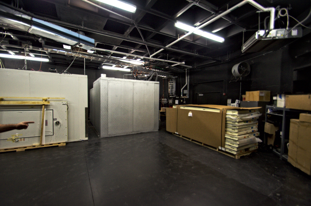
Before installing the HPF thermal enclosure. You can see a) the HRS enclosure (white box on the left), b) the HPF calibration enclosure (silver box in the middle), c) some of the new uninstalled HPF enclosure panels, and d) the open area where the HPF enclosure will sit.
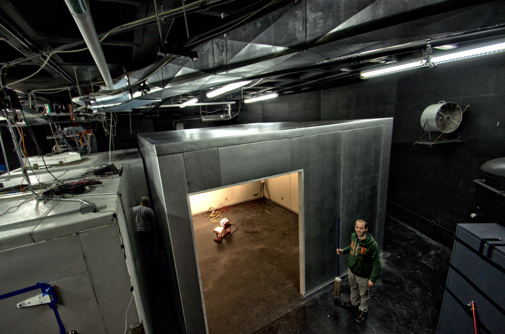
After installation: The HPF will sit inside this enclosure inside a clean room (not installed yet!) on the far side seen from this angle. A 6 foot sliding door – big enough for the HPF to get through – will cover up the remaining opening.
Moreover, you can see a short time-lapse video of the setup process right here:
Preliminary temperature monitoring system
During the last day we installed a temperature monitoring system (see figure below) devised by HPF team member Paul Robertson to measure temperatures at 6 places: high and low a) inside the Spectrograph Room, b) inside the Calibration Enclosure and c) inside the newly installed HPF enclosure. The placement of the sensors are summarized in the illustration below:
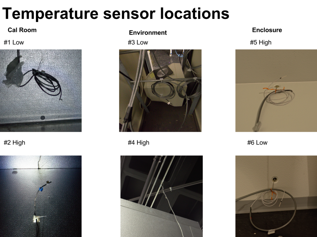
Temperature sensor locations: Locations of the 6 PT-100 temperature sensors placed in 3 different locations high and low, summarized above.
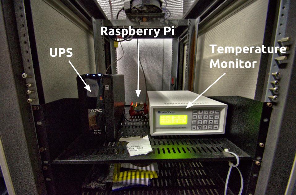
The temperature monitoring system: a) An Uninterrupted Power Supply (UPS), gracefully supplied by the Observatory, so if there is ever a power outage we can still monitor the temperature! b) Raspberry Pi computer that logs the temperature from c) the LakeShore temperature monitor which interfaces with the 6 PT-100 temperatures mentioned above.
Nominally, the temperature in the Spectrograph Room is controlled to +-0.3°C, but we wanted to assess this independently, as any temperature changes will cause instrumental drifts, causing the overall radial-velocity precision to degrade. More specifically, our goals of installing the system were to monitor and gain insights into the following:
a) Low frequency temperature variations: These are long-baseline temperature changes, variations longer than a week. The temperature changes between the seasons are a good example. Do these drifts show up at all? If so, at what amplitudes? These questions are interesting as these drifts are the ones that HPF will notice, and where the active temperature control system will come in to compensate.
b) High frequency temperature variations: These are temperature variations around a day or less. Let’s say somebody opens the door to the outside and lets cool air come into the Spectrograph Room in the winter: we observe a temperature dip. In the summer: a temperature spike. Let’s face it: these variations are probably always going to be present. This is exactly why we have to install the thermal enclosure – to buffer these temperature fluctuations out. And, moreover, we want to install the system to get a concrete feel for how how effective these enclosures (the HPF and calibration enclosure) are at buffering out these high-frequency temperature variations.
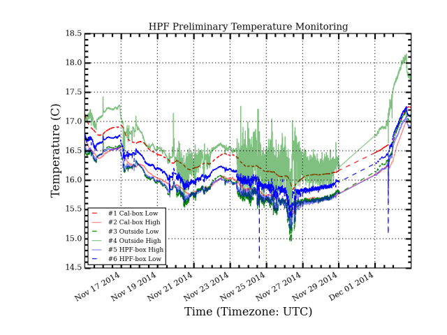
Below we plot the first few days of temperature data obtained:
From the temperature plot above we can see the following:
1) The Calibration box (red curves), which is completely closed, shows that it very effectively buffers out high-frequency temperature changes in the Spectrograph Room (green curves).
2) The Calibration box (red curves) drifts with the longer-term temperature changes, as expected, but these same long-term temperature variations are higher than expected from the +/- 0.3°C control setpoint. This issue is currently under consideration. We will continue to monitor the temperatures carefully over the next months.

 RSS - Posts