Keeping it Cool

The Habitable Zone Planet Finder, being an infrared spectrograph, must be kept from being saturated by infrared radiation emitted from the surroundings. This can be done by keeping the instrument extremely cold–180K, to be precise.  It must be kept at that fixed temperature to milli-Kelvin precision, as any variations will increase RV measurement errors. How do we achieve this? Take a look at the figure below.

The HPF radiation shield

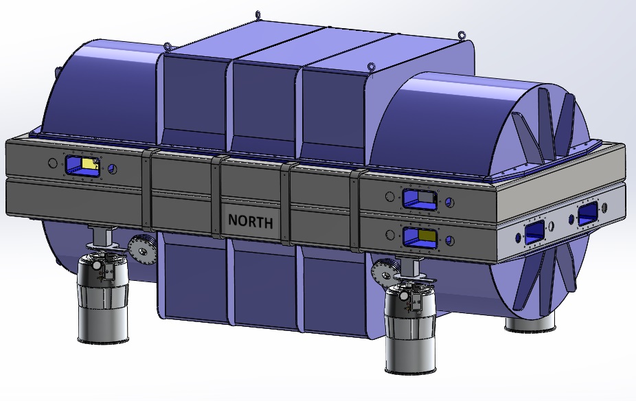
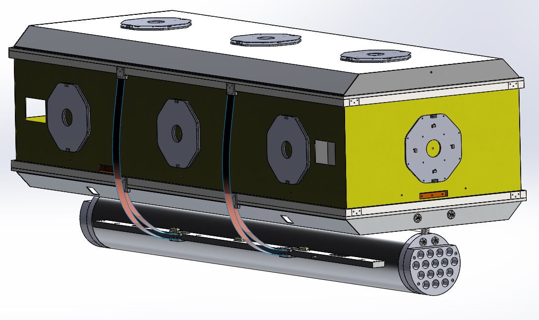
The HPF radiation shield – a vacuum chamber which contains the instrument optics – along with the liquid nitrogen (LN2) tank are both covered in MLI blankets for thermal insulation, and along with the copper thermal straps and the heater panels, they are responsible for keeping HPF at 180K with milli-Kelvin precision.

We need to consider four things:

  1. Cooling agent – We use liquid nitrogen (LN2) to cool the instrument. The LN2 tank is at a fixed temperature of 77K at atmospheric pressure.
  2. Conductive paths to the vacuum chamber – To cool down the radiation shield, we connect it with the LN2 tank with highly thermally conductive copper thermal straps. The straps need to be sized properly to not draw too much heat (resulting in a too cold chamber), nor too little heat (chamber too warm) from the vacuum chamber over long periods of time. The copper straps are sized to cool the vacuum chamber down to temperatures slightly cooler (around 160K – 170K) than the 180K end temperature goal.
  3. Heater Panels – These panels heat the over-cooled radiation shield to the 180K temperature goal, and at the same time give us the milli-Kelvin precision required.
  4. Thermal Insulation – Lastly, all of the above components are kept under high vacuum, and are all covered with Multi-Layer Insulation blankets (MLI–commonly used for space probes!), to provide effective thermal insulation from the outside world.

Radiative equilibrium

The radiation shield is on one hand being heated up by the radiation from the surroundings (at room temperature) and by the heater panels, and being cooled down from the copper thermal straps on the other. At equilibrium we can write:

H_{\mathrm{rad}}+H_{\mathrm{Heaters}}=H_{\mathrm{Cu}}

where H_{\mathrm{rad}}, H_{\mathrm{Heaters}}, H_{\mathrm{Cu}}, denote the heat current from the net incoming radiation, the heaters, and the copper straps, respectively. Each of these factors are discussed below; this discussion might be a bit on the technical side – if so, feel free to skip to the bottom to see pictures from the copper thermal strap and heater panel preparation.

I. Incoming radiation

First off, let’s consider the incoming radiation. All objects, regardless of their temperature, emit energy in the form of electromagnetic radiation: the warmth of the Sun and glowing coals in a fireplace are just infrared radiation emitted from these objects.

Then to the math. The net heat current absorbed by an object with surface area A and emissivity e_{\mathrm{eff}} (a dimensionless number between 0 and 1–larger for darker surfaces) sitting in a room at absolute temperature T_{\mathrm{room}}, can be expressed by the Stefan-Boltzmann law:

H_{\mathrm{rad}} = A e_{\mathrm{eff}} \sigma (T_{\mathrm{room}}^4 - T_{\mathrm{HPF}}^{4})

where T_{\mathrm{HPF}} is the absolute temperature our object: the HPF instrument.

The emissivity of MLI blankets is very low (for good blankets 0.005 \lesssim e \lesssim 0.1; see here) and therefore offer very good radiative thermal insulation. By covering HPF in MLI blankets, the emissivity of the blankets governs e_{\mathrm{eff}}, the effective emissivity of the instrument. However, the actual value of e_{\mathrm{eff}} is highly dependent on the overall quality of the MLI blankets and the surface finish of the radiation shield, etc., and it is very difficult to calculate the exact value correctly. Our best bet, then, is to empirically derive the effective emissivity from the APOGEE instrument built for the Sloan Digital Sky Survey. This gives us a value of e_{\mathrm{eff}} \sim 0.0087. We will defer further MLI-blanket discussion–how we prepare and size the blankets for HPF–until later; it is material for a whole blog post in itself!

II. Cooling with Copper

When a quantity of heat dQ is transferred through a conductive material in time dt, the rate of heat flow is given by H=\frac{dQ}{dt}. More specifically, we can relate the heat current to other properties of our copper thermal straps with the following equation:

H_{\mathrm{Cu}}=\frac{dQ}{dt}=kA\frac{T_{H}-T_{C}}{L}

where k is the thermal conductivity of the material (copper in our case) and T_C = 77 K is the LN2 temperature, and T_H = 180 K is the radiation shield temperature, and L and A are the length and cross-sectional area of our thermal strap, respectively.

There is one issue, however: the thermal conductivity of copper varies with temperature, so k is not a constant in our operating temperature range (see figure below). By integrating over the temperature range:

H_{\mathrm{Cu}}=\frac{dQ}{dt}=\frac{A}{L}\int_{T_C}^{T_H}k(T)dT,

we can account for this secondary effect – ignoring it, we would underestimate H_{\mathrm{Cu}}.

The thermal conductivity of copper as a function of temperature

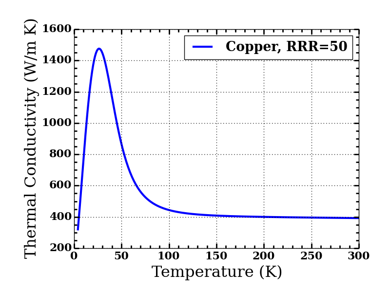
The thermal conductivity of copper as a function of temperature: We see a non-negligible change in thermal conductivity in the relevant temperature range for the HPF thermal copper strap; 77K to 180K. Data obtained from NIST’s cryogenic website – see here – assuming a Residual-Resistance Ratio (RRR) of 50 [RRR wiki – here].

The images below show a few photos from the copper strap preparation; we will need 16 straps in total.

Milled and cut copper terminals

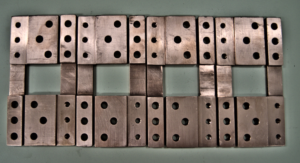
Milled and cut copper terminals: Cut and milled 110 multipurpose copper sheets, using a water jet, and a standard mill.
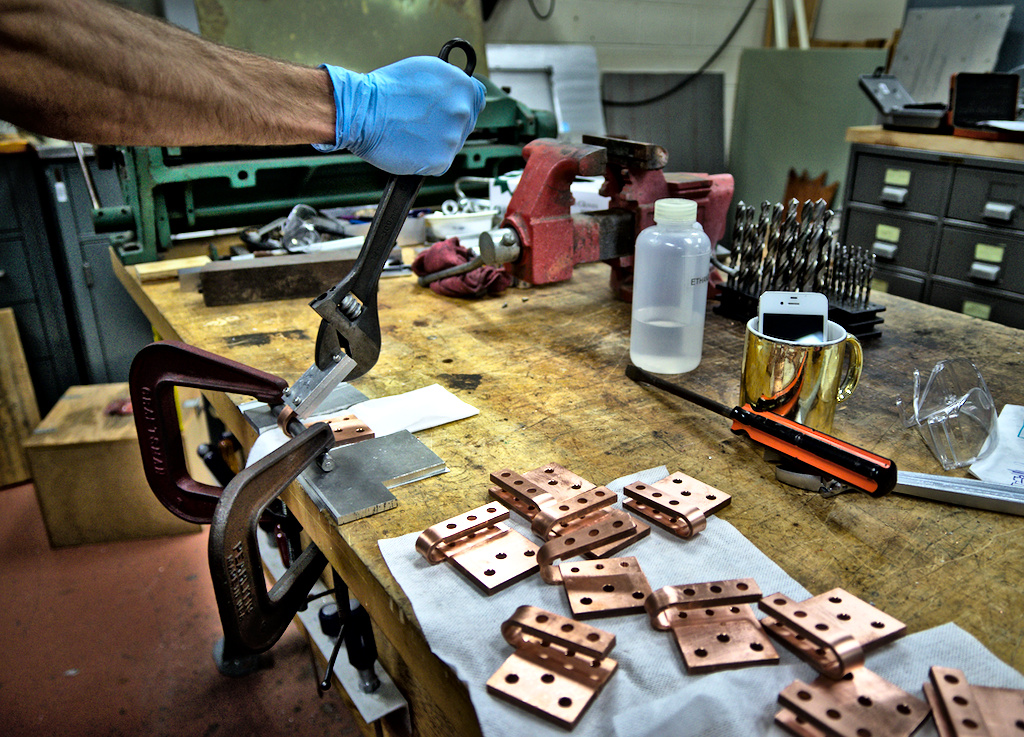
Bending Cu terminals

Bending Copper

A test Cu thermal strap

A test Cu thermal strap

III. Heater Panels

Like mentioned above, the heater panels heat up the overcooled radiation shield to the 180K temperature goal. Each panel has 4 thermal resistors (150Ω each), which heat up in proportion to the electrical current going through them. As we now know the heat current from (I) the net incoming radiation, and (II) the copper straps, we can calculate the heat current needed from the heater panels to keep the system at equilibrium:

H_{\mathrm{Heaters}}=H_{\mathrm{Cu}}-H_{\mathrm{rad}},

which can be used to calculate the current needed per panel and per thermal resistor. The exact current running through per resistor is controlled by a thermal feedback control system which monitors any external temperature fluctuations at the observatory–we can’t control the weather! The system then compensates for these changes by controlling the amount of electrical current going through the resistors, warming them up as needed, keeping the instrument stable at 180K with the milli-Kelvin precision needed.

Tapping stage; each panel has 24 holes to be tapped; so that they can be bolted securely and with good contact to the radiation shield.

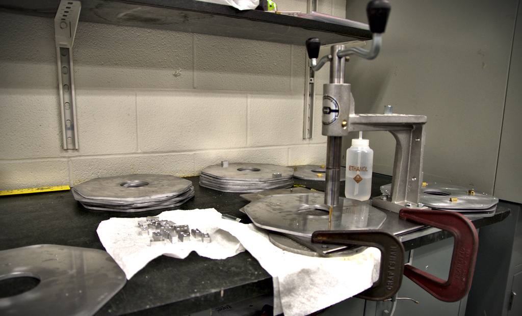
Thermal panel production: Tapping stage; each panel has 24 holes to be tapped; so that they can be bolted securely and with good contact to the radiation shield.

Aluminum Heater Panels

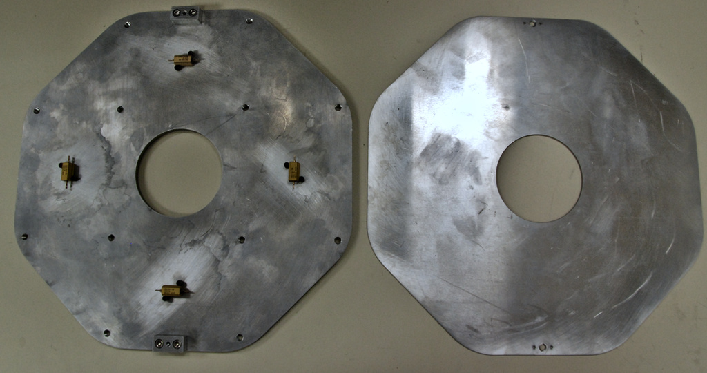
Aluminum Heater Panels:14 panels in total, each of which have 4 thermal resistors connected to the temperature feedback control system which is capable for keeping HPF stable at 180K.

Posted in HPF Hardware | Comments Off on Keeping it Cool

The HPF Cryostat Design

Now that you know what HPF is, and what its primary science functions will be, let’s take a closer look at some of the hardware that makes the exciting science possible. The cryostat–basically, a cryogenic vacuum chamber–is fed light from the telescope via an optical fiber, which then passes through the spectrograph optics before being imaged onto the infrared detector. “But wait,” you might ask, “if this is infrared light we’re trying to detect, how do you filter out the infrared light being emitted from around the room?” After all, warm objects emit infrared. This phenomenon, where too much IR light reaches a detector face, is known as saturation. So much IR reaches the detector, that it becomes impossible to discern the spectra of one object from the next. To remedy this, we build a vacuum chamber. This is the exoskeleton that will house all of the optics, keeping them cold and isolated from the rest of the world. Remember, we’re trying to maintain 1 milliKelvin stability (5 parts per million!), and so the more control we have over heat transfer within the system, the better. The cryostat vacuum chamber is a right circular cylinder, with a rectangular flange which allows the upper and lower lids to be removed. Air is evacuated from the chamber; the pressure within reaching 10-7 millitorr levels.

Full Cryostat, resting on isolation legs.

Full Cryostat, resting on isolation legs.

There are 3 modes of heat transfer, and they govern all heat transfer throughout the universe: conduction, convection, and radiation. Conduction is the transfer of heat through physical contact. Convection is the transfer of heat through a liquid or gas medium surrounding an object. Radiation is the transfer of energy through photons.

In an ideal world, the HPF cryostat would eliminate all three of these heat transfer modes. In reality, we can only limit their effects, but cannot altogether eliminate them. In order to limit conductive pathways from the optical components to the surrounding cryostat shell, we use a small cross section suspension system. A set of 3 “hangers” allows the bench, with the optics mounted on top, to be nearly conductively insulated from the surrounding cryostat body. This three point mounting system also allows the bench to thermally contract, without inducing any stresses on the system, which would wreak havoc on optical alignment.

By evacuating air from the cryostat, we essentially eliminate convective heat transfer. Without air surrounding the optics, there is no medium to flow over the optical components and transfer energy. That leaves us with radiation, our primary concern. In order to keep the detector from being saturated with IR radiation, we must keep all objects that the detector sees extremely cold… 180 Kelvin (-136 degrees Fahrenheit) cold.

To isolate the optics from the surrounding world, a radiation shield is employed. This radiation shield acts like a buffer between the cryostat body, and the optical components residing inside. With the use of multi-layer insulation blankets made of highly reflective material, the radiative load on the shield will be decreased to a level of 3.5 watts per square meter. The radiation shield is coupled via 16 thermal straps of copper foil to a liquid nitrogen tank, effectively creating a large heat sink. The copper straps are sized in such a way that the equilibrium temperature of the radiation shield is 175 degrees Kelvin. To get the shield to be 180 K, we use a set of 14 heater panels, adding just enough heat to control the shield to 180 K. With the optics now being surrounding by material at 180 K, they too will drift to a temperature of 180 K.

Radiation shield with liquid nitrogen tank, heater panels (stop sign shapes), and thermal straps connection nitrogen tank to radiation shield.

Radiation shield with liquid nitrogen tank, heater panels (stop sign shapes), and thermal straps connection nitrogen tank to radiation shield.

By putting the optics in a vacuum chamber, limiting the conductive paths, and actively controlling the radiation shield temperature, the HPF team will be able to achieve 1 milliKelvin temperature stability over long time scales.


Posted in HPF Hardware | Comments Off on The HPF Cryostat Design

HPF at the USA Science & Engineering Festival

This weekend the HPF group was hard at work at the 3rd USA Science & Engineering Festival, the largest celebration of science and engineering in the United States. Members of the HPF group also attended the previous event in 2012. Over 300,000 people of all ages and disciplines attended this four-day STEM festival in Washington D.C. The event included over 3000 hands-on activities and demonstrations from scientists and engineers from both universities and industry. A group of HPF graduate students, Ryan Terrien, Arpita Roy, Sam Halverson, and Rob Marchwinski, traveled to the festival along with faculty member Dr Chris Palma, and joined a large group of Penn State scientists presenting interactive demonstrations.

Rob Marchwinski and Ryan Terrien aligning the infrared camera. Lab coats are essential for successful public outreach.

The HPF team built a simplified layout of the HPF instrument, which included optical fibers, real echelle and holographic diffraction gratings, and a crowd-pleasing infrared camera. Over 800 visitors from all ages stopped by the PSU booth and learned about the technology behind HPF and its hunt for planets.

Graduate student Sam Halverson aligns optical elements for the echelle and holographic diffraction grating demonstrations

2014-04-28 12.04.39

Graduate students Arpita Roy and Ryan Terrien discuss some of the technology used in the HPF instrument with some future scientists.

The PSU group even got a visit from the Nittany Lion!

The Nittany Lion looks over the HPF display.

The Nittany Lion looks over the HPF display.


Posted in HPF Science, Public Outreach | Comments Off on HPF at the USA Science & Engineering Festival